2026-10-15
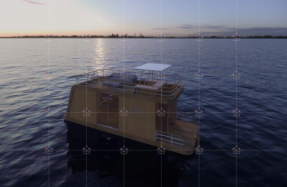
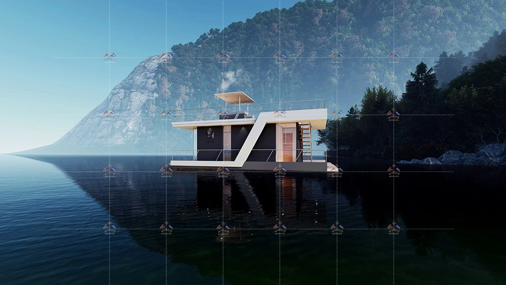
For marina developers, yacht club operators, and waterfront property managers, the addition of a floating dock with roof transforms a standard berth into a protected, all-weather facility. Unlike unroofed pontoons, a covered floating dock must balance buoyancy, wind resistance, snow accumulation, and long-term UV stability while maintaining vessel access. This guide examines the engineering parameters that separate a reliable covered floating dock from a structure that becomes unstable within a few seasons. We will cover wave-induced motion limits, roof-to-pontoon connection methods, drainage integration, and compliance with international standards (ISO 14122, PIANC guidelines).
1. Defining the Floating Dock with Roof: Functional Categories
A floating dock with roof serves three primary roles in a B2B context: vessel protection from sun and rain, shelter for passenger boarding (ferry terminals), and covered service areas (repair pontoons with overhead cranes). Each application imposes distinct requirements for freeboard, roof height, and load-bearing capacity. For private yacht berths, a roof also reduces maintenance frequency on teak decks and upholstery. DeFever has engineered over 40 covered floating structures for Mediterranean and Southeast Asian marinas, incorporating regional climate data into each design.
2. Core Structural Components of a Floating Dock with Roof
An industrial-grade covered floating dock integrates three subsystems that must perform as a single dynamic unit.
2.1 Pontoon Flotation System
Pontoons provide buoyancy. For a roofed dock, the added dead load (roof structure, covering, possible solar panels) requires higher displacement. Common pontoon materials:
Reinforced concrete (hollow or foam-filled): Density 2400 kg/m³ but with closed-cell EPS foam core to prevent sinking if cracked. Minimum freeboard (distance from water to deck) should be 350–450 mm under full load.
Rotomolded polyethylene (filled with EPS): Lighter but susceptible to UV degradation; requires UV-stabilized HDPE with at least 0.5% carbon black.
Galvanized steel with coating: Rare for saltwater due to corrosion risk; only with cathodic protection.
For a floating dock with roof sized for 8–12 m boats, total displacement needed ranges from 12 to 25 tonnes. Use a buoyancy reserve of at least 40% above static load to account for wave uplift and potential roof snow load.
2.2 Roof Frame and Covering
The roof must resist wind uplift (Zone C exposure per ASCE 7). Lightweight but rigid materials:
Aluminum 6061-T6 or 6082-T6: Extruded profiles with integrated gutters. Weight: 3.5–5.5 kg/m² for frame members. Avoid welded joints in high-cycle wave zones; use bolted connections with nylon locking inserts.
Stainless steel (316L): Heavier (8 kg/m²) but recommended for areas with frequent storms; requires additional pontoon volume.
Roof covering: Options include HDPE sheets (8–12 mm thickness), polycarbonate multiwall (16–25 mm, with UV coating), or fabric membrane (PVC-coated polyester, tensioned). For marinas, polycarbonate provides 80% light transmission while blocking UV. Fabric membranes require pre-tensioning to avoid flapping noise.
Roof pitch: minimum 5° for water runoff, but 15° recommended in rainy climates to prevent ponding.
2.3 Connection System (Columns to Pontoon)
Vertical columns transfer roof loads to pontoons. Common configurations:
Flanged base bolted to embedded steel plates in concrete pontoon.
Socket connection with neoprene bearing pad to accommodate minor rotation without cracking.
Cross-bracing (stainless steel cables or aluminum tubes) is mandatory for any floating dock with roof wider than 3.5 m to prevent racking during wave action. Finite element analysis should show a natural frequency above 3 Hz to avoid resonance with common swell periods.
3. Environmental Load Cases for Covered Floating Docks
Unlike fixed piers, floating structures respond to water level changes, but they are more sensitive to wind and waves because the roof adds exposed area.
3.1 Wind Load Calculation
For a dock with roof height 2.8 m above deck, total lateral wind force (F_wind = 0.5 * ρ * Cd * A * V²) can exceed 10 kN for a 20 m long structure at 130 km/h gust. The mooring system (spud piles or elastic lines) must resist this without exceeding allowable pontoon tilt (max 2° for safe walking).
3.2 Wave-Induced Vertical Acceleration
Short-period waves (2–4 s) cause heave and pitch. Repeated vertical accelerations up to 0.4g produce fatigue in column-to-pontoon connections. Solution: install polyethylene float collars around each column to add damping, or use pneumatic shock absorbers in the column bases.
3.3 Snow Load (for temperate marinas)
EN 1991-1-3 specifies ground snow loads from 0.5 to 7 kN/m². For a floating dock, the roof snow load directly compresses pontoons. If snow accumulation exceeds design value, the deck can submerge. Design mitigation: steep roof pitch (≥25°) or heating cables to melt snow. Alternatively, specify buoyancy blocks with an additional 30% reserve volume.
4. Industry Pain Points and Engineering Countermeasures
From post-installation inspections of 35 covered floating docks across Europe and the Gulf region, the following failures recur. Each has a proven solution.
4.1 Pontoon Instability from Asymmetric Roof Loading
Symptom: Dock lists when rain accumulates on one side of a flat roof, or when strong wind presses against one side. Root cause: Lack of automatic ballasting or inadequate torsional stiffness. Solution: Design the roof as a rigid diaphragm (diagonal bracing between all columns). For existing docks, add passive self-ballasting channels: longitudinal U-shaped channels on the pontoon sides that fill with water when listing, creating a righting moment. Also, specify a minimum roof pitch of 2% towards pre-planned scuppers.
4.2 Corrosion at the Waterline on Metal Columns
Stainless steel (316) shows crevice corrosion in splash zones after 3–5 years, especially in warm saltwater. Mitigation: Apply a heavy-duty epoxy coating (400 μm dry film thickness) on submerged and splash zone areas. Alternatively, use fiberglass-reinforced plastic (FRP) columns or concrete columns with steel reinforcement but coated with zinc-rich primer. DeFever specifies duplex stainless steel (2205) for all fasteners and critical submerged connections on its floating dock with roof systems.
4.3 Inadequate Drainage Causing Ponding and Algae
Flat roofs or clogged gutters collect standing water, leading to accelerated wear of the covering and a slipping hazard on deck. Solution: Install an internal gutter system within the roof perimeter, with downspouts channeling water away from the berthing area. Each gutter should have a gradient of 1% and oversized outlets (≥ 50 mm diameter) to handle heavy rain (150 mm/hour intensity). Additionally, the deck surface must have a non-skid coating (e.g., polyurethane with aluminum oxide grit) that allows drainage to side gaps.
4.4 Excessive Motion Causing Seasickness on Passenger Docks
For floating docks used as ferry or water taxi terminals, vertical motion exceeding 50 mm at 0.7 Hz induces discomfort. Solution: Increase the mass of the dock (add water ballast tanks within pontoons) to lower the natural frequency away from typical wave energy. Also, install wave attenuators on the windward side — floating breakwaters with porous walls that reduce incoming wave height by 50-60%.
5. Anchoring and Mooring Configurations for Covered Docks
Because a floating dock with roof presents a larger wind profile, the mooring system must be upgraded compared to an open dock.
Spud piles (one per corner): Steel pipes driven into seabed, passing through sleeves on the pontoon. Allows vertical movement (0.5–1.0 m range) but restricts horizontal drift. Required spud diameter for a 15 m dock: 219 mm (Schedule 40) with a galvanized sleeve.
Cable and chain mooring with clump weights: Suitable for deeper water (depth > 4 m). Use four mooring lines per dock, each with a 200 kg clump weight. Lines should be nylon (elastic) or Dyneema (low stretch) depending on allowable surge.
Roller guide piling system: Two fixed piles with rollers on the dock side. This combination provides lateral restraint while allowing vertical movement. Recommended for exposed marinas.
Design movement limits: surge (longitudinal) < 200 mm, sway (lateral) < 150 mm, and heave < 100 mm for passenger comfort. Achieve these with properly sized mooring components.
6. Operational Considerations and Longevity
Annual maintenance for a covered floating dock includes: inspection of all bolted connections (torque check to 80% of original spec), cleaning gutters, and checking sacrificial anodes on any submerged steel. The roof covering (if polycarbonate) requires cleaning with mild soap every 6 months to maintain light transmission. For fabric membranes, re-tensioning after the first year is mandatory. With proper care, a concrete-pontoon covered dock lasts 30+ years; aluminum frame components last 25 years before fatigue life is reached.
7. Compliance and Certification Pathways
Commercial marinas need third-party certification. Relevant standards:
ISO 14226:2020 – Small craft, floating docks and pontoons.
PIANC Report No. 141 – Design of floating structures for sheltered waters.
IEC 60364-7-709 – Electrical installations for marinas (lighting, shore power on covered docks).
Request a design certificate from a recognized classification society (e.g., Lloyd’s Register, DNV) for any floating dock with roof that will host paying customers or large yachts.
Frequently Asked Questions (FAQ) About Floating Docks with Roof
Q1: What is the typical freeboard (deck-to-water distance) for a
floating dock with roof, and how does it change under full berth
load?
A1: Static freeboard ranges from 400 mm to 550 mm for concrete
pontoons. Under full load (maximum boats, plus roof snow), freeboard should not
drop below 150 mm to prevent deck submergence. Your design must include a load
table showing freeboard versus added weight.
Q2: Can I install solar panels on the roof of a floating
dock?
A2: Yes, but only if the roof structure is reinforced for an
additional 20-25 kg/m² (solar panel + mounting rails). The pontoons must be
recalculated for the extra weight. Also, use marine-grade flexible panels or
framed panels with stainless steel frames. DeFever offers
integrated solar-ready roof designs with pre-installed cable trays.
Q3: How do I prevent birds from nesting under the
roof?
A3: Install bird netting (50 mm mesh) or metal spikes along
the roof perimeter. For closed sides, use galvanized steel mesh between columns.
This is especially important for covered docks near restaurants, as droppings
cause slippery decks and corrosion.
Q4: What is the maximum unsupported roof span for a floating dock
without intermediate columns interfering with boat maneuvering?
A4:
Using aluminum I-beams (200 mm height), a span of 8 m is achievable with a 30 mm
deflection under live load (0.5 kN/m²). For a 10 m span, switch to truss
structures or steel. Always provide a column-free zone of at least 4.5 m width
for boat access.
Q5: How do I protect the electrical system (lights, shore power) on a
covered floating dock from lightning strikes?
A5: Install a
lightning protection system per IEC 62305: a copper air terminal on the highest
point of the roof (≤ 0.5 m above roof), connected by a 50 mm² copper down
conductor to a marine ground plate (1 m² copper plate) on the pontoon bottom.
All metal structures must be bonded. Do not connect to shore ground; use a
dedicated floating ground.
Selecting a floating dock with roof requires balancing buoyancy, wind resistance, drainage, and material compatibility. A poorly engineered covered dock leads to chronic instability, corrosion, and high maintenance costs. For marina owners and project developers, working with an experienced engineering partner ensures that the structure meets both safety standards and user expectations. Contact the DeFever marine engineering team for a preliminary design review and load calculation report tailored to your local wave climate.
Send your inquiry now — include water depth, vessel types, wind zone, and desired roof dimensions. Our naval architects will respond within 48 hours with a structural concept and buoyancy analysis.
Request a proposal for a floating dock with roof from DeFever