
DeFever has engineered and installed marine infrastructure for over 35 years, serving yacht harbours, commercial ports, and waterfront developments worldwide. This technical guide examines the floating dock as a critical asset for sites with significant water level fluctuations – including tidal ranges, reservoir drawdown, and river stage variations. We will cover buoyancy reserve calculations, mooring system design, material durability (concrete, aluminum, composite), load ratings, and solutions to common operational problems such as excessive motion, structural fatigue, and anchorage failure.
1. Defining the Floating Dock: Buoyancy Principle and Functional Advantages
The floating dock is a platform that rests on the water surface, supported by airtight pontoons or foam-filled chambers. Unlike fixed piers, a floating structure rises and falls with the water level, maintaining a constant freeboard (typically 300–600mm above water). This makes it the only practical solution for:
Reservoirs and dams with seasonal drawdown of 5–20 metres.
Estuaries and tidal rivers with 2–8 metre tidal ranges.
Lakes with fluctuating water levels due to hydroelectric operations.
Areas with soft or erodible bottoms where piling is not feasible.
The buoyancy of the floating dock is provided by displacement. Each pontoon must have sufficient reserve buoyancy (typically 40–60% of its submerged volume) to support the design live load plus a safety margin. For a standard marina dock, a reserve buoyancy ratio of 1.5 to 2.0 (i.e., the pontoon can support 1.5–2 times its own weight plus dead load) is required by classification societies such as PIANC and ISO 28460.
2. Buoyancy Calculation and Pontoon Configuration
Professional engineering of the floating dock begins with accurate buoyancy analysis. The total required buoyant volume (V) is calculated as:
V = (W_dead + W_live) / (ρ_water × g × SF)
Where:
W_dead = self-weight of dock structure (deck, pontoons, fittings).
W_live = design live load (typically 3–5 kN/m² for pedestrian marinas; 10–15 kN/m² for vehicle access or crane pads).
ρ_water = density (freshwater 1000 kg/m³; seawater 1025 kg/m³).
g = 9.81 m/s².
SF = safety factor (1.4 for normal operation; 1.8 for storm conditions).
Common pontoon configurations:
Concrete pontoons (hollow, reinforced): 40–60 year service life. Buoyancy provided by internal air chambers; must be inspected for water ingress.
Rotomoulded polyethylene pontoons: Lightweight, corrosion-proof, but UV degradation after 15–20 years. Filled with closed-cell EPS foam (guarantees positive buoyancy even if shell is punctured).
Aluminum pontoons: Welded marine-grade 5083 H321 alloy. Excellent strength-to-weight ratio, but require anti-fouling coating and cathodic protection in saltwater.
For heavy-duty applications (commercial ferry landings, fuel docks), concrete pontoons with 450mm freeboard and 600mm draft are standard. DeFever uses precast concrete elements with high-performance concrete (C40/50) and epoxy-coated rebar for 100-year design life.
3. Anchoring and Mooring Systems for Floating Docks
A floating dock without an effective anchoring system is unsafe. The anchorage must restrain the dock against wind, wave, current, and vessel berthing forces while allowing vertical movement. Four primary systems are used professionally:
Pile-guided system: Steel or concrete piles driven into the seabed; the dock slides vertically on pile guides (polyethylene or bronze bushings). Best for large tidal ranges (≥ 3m) and high wave energy. Pile spacing typically 6–12 metres.
Spud pole system: Vertical steel poles (spuds) attached to the dock that penetrate the bottom. Suitable for sheltered waters with soft sediment. Spud diameter 150–300mm; must be raised for dredging or dock relocation.
Cable / chain mooring: Anchor chains or wire ropes connecting dock corners to seabed anchors (deadweight, screw anchors, or driven piles). Requires slack to allow vertical movement; used in lakes and reservoirs with minimal current.
Combined system (piles + mooring lines): Provides redundancy in high-current locations (e.g., river marinas). Mooring lines limit lateral drift; piles guide vertical movement.
Anchor holding capacity must be verified by soil testing. For example, a screw anchor (helical pile) in medium-dense sand can provide 50–100 kN pullout resistance. Chain diameter for a 20-tonne floating dock in a 1-knot current: minimum 16mm Grade 43 (U2) chain. Project cases from DeFever demonstrate successful installations using all four methods across varying geotechnical conditions.
4. Load Capacity and Structural Standards
Professional marina operators require certified load ratings for the floating dock. The following standards apply:
ISO 28460 (Petroleum and natural gas industries – Marine loading arms): Used for commercial docks, specifying uniform live load of 50 kN/m² for cargo transfer areas.
PIANC (World Association for Waterborne Transport Infrastructure) guidelines: For recreational marinas: 3.0 kN/m² (uniform) plus a 50 kN point load for vehicle access.
ASCE 7-16 (Minimum Design Loads for Docks): Includes wave loads, current loads, and berthing impact loads.
Load testing is performed using water bags or calibrated weights. Deflection under design live load must not exceed L/200 (e.g., 15mm for a 3m span). Permanent deflection (creep) after unloading should be less than 2mm for concrete docks. For aluminum docks, limit elastic deflection to L/300.
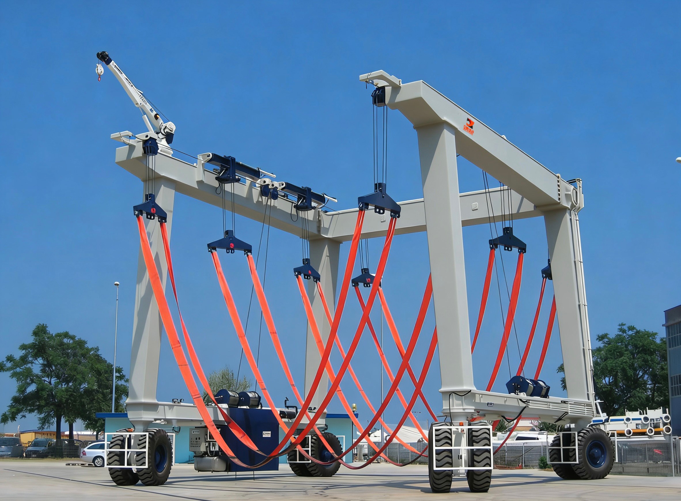
Special consideration: crane pads or mobile hoists on floating docks require local reinforcement. A 20-tonne mobile crane on a concrete pontoon requires a spreader plate (1.5m × 1.5m) and a pontoon with double reinforcement (600mm depth, 8% steel ratio). DeFever project cases include load-certified floating docks for superyacht maintenance facilities.
5. Material Selection for Durability in Marine Environments
Corrosion, UV degradation, and marine borer attack are the primary threats to the floating dock. Each material has specific advantages and protection requirements:
Reinforced concrete: Use sulfate-resistant cement (Type V), maximum w/c ratio 0.40, minimum cover 50mm for rebar, and microsilica (8% by mass) to reduce chloride ingress. For saltwater, apply a silane sealer every 5–7 years. Concrete is immune to marine borers (teredo navalis).
Marine-grade aluminum (5083 H321): Excellent corrosion resistance in saltwater due to passive oxide layer. Avoid contact with copper-based anti-fouling paints (galvanic corrosion). Use anodic protection with aluminum or zinc sacrificial anodes (replaced every 2–3 years).
Galvanized steel: Only for freshwater or temporary docks. Hot-dip galvanizing (minimum 600 g/m²) provides 15–20 years in freshwater; in saltwater, expect pitting within 5 years unless coated with epoxy and regularly maintained.
Composite (FRP – fibreglass reinforced polymer): High initial cost but zero corrosion and low maintenance. UV-stabilized resin (add HALS) required for sunlight exposure. Composite pontoons are typically foam-filled and can be 40% lighter than concrete.
For decking surfaces, specify 50mm thick timber (Bangkirai, Cumaru, or heat-treated ash) with stainless steel screws (A4-316). Alternative: extruded aluminum decking with slip-resistant grooves (coefficient of friction ≥ 0.6).
6. Industry Pain Points: Motion, Fatigue, and Anchorage Failure
Even well-designed floating docks encounter operational problems. Below are common issues and engineering solutions based on field data from DeFever projects.
6.1 Excessive Vertical Motion (Heave) in Waves
Heave amplitudes exceeding ±200mm make boarding dangerous. Causes: insufficient mass (lightweight pontoons) or wave period matching dock natural frequency. Solution: increase pontoon draft (add ballast water to lower centre of gravity) or install wave attenuators (floating breakwaters) upwind. For high-wave-energy locations, change from a cable-moored dock to a pile-guided system, which reduces heave by 50–70%.
6.2 Structural Fatigue Cracking (Aluminum Docks)
Aluminum welded joints can crack after 10–15 years of continuous wave action. Cracks typically initiate at weld toes. Solution: specify post-weld heat treatment (PWHT) for aluminum; use larger radius fillet welds (≥ 6mm); and conduct non-destructive testing (dye penetrant) every 3 years. Retrofit with doubler plates on high-stress corners.
6.3 Anchor Chain Abrasion and Corrosion
Chains rubbing against rocks or concrete edges wear down rapidly. Solution: install chain protectors (polyurethane sleeves) and replace chains every 5–7 years in saltwater. Use stud-link chain (ISO 1704) instead of open-link for higher abrasion resistance. For concrete docks, embed stainless steel rubbing strips at chain contact points.
6.4 Pontoon Water Ingress (Concrete or Plastic)
Water inside a pontoon destroys buoyancy and adds dead load. Causes: cracks, failed seals, or puncture. Solution: install inspection ports and automatic bilge pumps with alarms. For new construction, specify closed-cell foam filling (min. density 32 kg/m³) that provides positive buoyancy even if shell is breached. Foam also reduces sloshing forces.
6.5 Dock Sway (Lateral Movement) During Berthing
Sway > 300mm makes mooring lines ineffective. Causes: insufficient lateral stiffness in mooring system. Solution: install diagonal mooring lines (two lines per corner at 45°) or add a second row of piles. For cable-moored docks, increase chain pre-tension to 10–15% of breaking strength.
7. Design for Specific Environments: Rivers, Reservoirs, and Tidal Zones
The floating dock must be adapted to local hydraulic conditions:
River marinas (current > 1 m/s): Use pile-guided system with piles spaced every 4–6 metres. Install current deflectors (V-shaped noses) on upstream pontoons. Increase mooring line diameter by 30% compared to lake designs.
Reservoirs with rapid drawdown (1 m/day): Floating docks must not ground out at minimum water level. Design with 1.0–1.5m freeboard range and a long, sloping gangway (1:4 ratio). Use a chain mooring system with a slack management device (submerged buoy).
Extreme tidal range (≥ 6m, e.g., Bay of Fundy): A single floating dock is impractical due to gangway length. Instead, use a combination of a fixed lower pier and an upper floating dock connected by a steep ramp (1:2) or a vertical lift system. Alternatively, use a floating dock that climbs on inclined piles (rack and pinion).
DeFever project cases include solutions for all three scenarios, with documented performance over 10+ years of operation.
8. Installation, Commissioning, and Maintenance Protocols
Professional installation of the floating dock requires:
Bathymetric survey and geotechnical investigation (SPT or CPT).
Assembly on land or in a dry dock, followed by controlled launch.
Positioning with tugboats and GPS (accuracy ±50mm).
Pile driving (if guided system) using vibratory hammer; vertical tolerance ±0.5%.
Chain mooring pre-tensioning using dynamometer (achieve specified tension ±10%).
Load test with water bags at 125% of design live load for 24 hours; measure residual deflection.
Maintenance schedule (per year):
Inspect all welds, bolts, and hinges for corrosion or loosening.
Measure freeboard at four corners; more than 30mm difference indicates uneven loading or water ingress.
Clean and grease pile guides (every 6 months for saltwater).
Diver inspection of underwater structure and anodes (annually).
Replace sacrificial anodes when 70% consumed.
9. Frequently Asked Questions (FAQ) – The Floating Dock
Q1: What is the typical lifespan of a floating dock in saltwater?
A1: For concrete pontoons with proper mix design (w/c ≤ 0.40, epoxy-coated rebar), 50–75 years. Aluminum docks last 30–40 years with anode replacement. Polyethylene docks typically 15–20 years before UV degradation requires replacement. Composite (FRP) docks exceed 50 years but have higher initial cost.
Q2: How do I calculate the required buoyancy reserve for a floating dock?
A2: A minimum reserve buoyancy ratio of 1.5 is required by PIANC for recreational marinas. For commercial docks with heavy mobile cranes, use 2.0. Calculation example: a 10-tonne dock (dead weight) with a 5-tonne live load (15 tonnes total) needs buoyant volume = (15,000 kg × 1.5) / 1000 kg/m³ = 22.5 m³. Each pontoon segment must provide at least that displacement at maximum draft.
Q3: Can a floating dock be used in areas with ice cover?
A3: Yes, but only with ice-resistant design. Use a pile-guided system with steel piles and a hydraulic lift mechanism that raises the dock above the ice. Alternatively, install bubble aeration systems (compressed air) to prevent ice formation around pontoons. In shallow lakes, remove the dock before winter. DeFever has supplied ice-compatible floating docks for Canadian and Scandinavian marinas.
Q4: What is the maximum vessel size that can berth alongside a floating dock?
A4: Vessel length is not the limiting factor; rather, it is the dock's load capacity and fender system. A standard 3m-wide floating dock with 5 kN/m² rating can accommodate vessels up to 30m LOA for pedestrian access. For superyachts (50m+), use a 5m-wide dock with 10 kN/m² rating, heavy-duty pneumatic fenders (1.2m diameter), and reinforced breasting dolphins. The dock itself must be able to withstand a berthing energy of 50–100 kNm.
Q5: How often should anchor chains be replaced on a floating dock?
A5: In saltwater, inspect chains annually for wear (measure link diameter). Replace when diameter reduction exceeds 10% of original. Average service life for galvanized chains (Grade 43) in temperate saltwater is 5–7 years; for stainless steel chains (A4-316), 15–20 years. For freshwater, galvanized chains last 15–20 years. Always use chain that is certified to ISO 1704.
Q6: What is the cost difference between a pile-guided and a cable-moored floating dock?
A6: For a 50m long, 3m wide dock, a pile-guided system (steel piles, guides, pile caps) costs approximately 40–60% more than a cable-moored system. However, the pile-guided system provides better motion control (50–70% less sway and surge) and requires less maintenance (no chain replacement every 5 years). For high-wave or high-current sites, the additional cost is justified. For sheltered lakes, a cable system is sufficient.
10. Inquiry – Engineering Consultation and Quotation for Floating Docks
Selecting the correct the floating dock design for your marina, commercial port, or waterfront development requires site-specific hydraulic data and load analysis. DeFever provides:
Custom pontoon engineering (concrete, aluminum, composite).
Anchoring system design (pile-guided, cable, spud, or hybrid).
Load certification to ISO, PIANC, or ASCE standards.
On-site installation supervision and commissioning.
Long-term maintenance contracts and inspection services.
Send your inquiry with the following details: water body type (salt/fresh), maximum water level variation (metres), design vessel size, intended live load (kN/m²), and a site plan with bathymetry if available. Our marine engineers will respond within 48 hours with a preliminary design, budget estimate, and case study references from similar projects.
Submit your technical inquiry now: Click here for the official inquiry form or visit our project cases page to see examples of floating dock installations worldwide.


