
For property owners, marina operators, and coastal developers, the distinction between a temporary waterfront structure and a durable maritime asset is defined by engineering rigor. The field of decks and docks construction has shifted from simple carpentry to a discipline requiring geotechnical analysis, corrosion science, and lifecycle asset management. Selecting the appropriate materials and structural systems determines whether a waterfront investment performs for decades or becomes a recurring liability.
The foundational decision in any waterfront project is material specification. Each environment presents distinct degradation mechanisms, and material choice must account for water chemistry, biological activity, and mechanical loads.
Southern yellow pine treated with micronized copper azole remains common for residential applications. However, the industry has documented that in saltwater environments, copper-based treatments accelerate galvanic corrosion on submerged steel fasteners and connectors. For timber structures in marine settings, specification requires:
Type 316 stainless steel bolts, nuts, and washers for all connections below the waterline
Hot-dipped galvanized connectors with ASTM A153 coating for above-water components
Annual inspection protocols for checking marine borer infestation in warm-water regions
Reinforced concrete offers the longest service life when properly engineered. Precast concrete decks and floating pontoon systems utilize high-strength concrete (6,000 psi minimum) with low water-to-cement ratios. Key specifications include:
Microsilica or fly ash admixtures to reduce permeability below 2,000 coulombs per ASTM C1202
Epoxy-coated or stainless steel rebar to prevent chloride-induced spalling
Post-tensioned designs that eliminate cracking and maintain structural integrity under dynamic loads
Marine-grade aluminum (6061-T6, 5086-H32) provides the highest strength-to-weight ratio, making it suitable for high-load applications such as fuel docks and commercial ferry landings. Composite piling systems using glass-fiber reinforced polymer (GFRP) have gained adoption in environmentally sensitive areas where driven piles might disturb protected habitats. These materials eliminate corrosion concerns entirely but require specialized connection details to prevent stress concentrations at fastening points.
Engineering firms like DeFever emphasize that material selection must be matched to specific site conditions, including tidal range, vessel traffic patterns, and freeze-thaw cycles. A specification appropriate for a freshwater lake will fail prematurely in a saltwater marina environment.
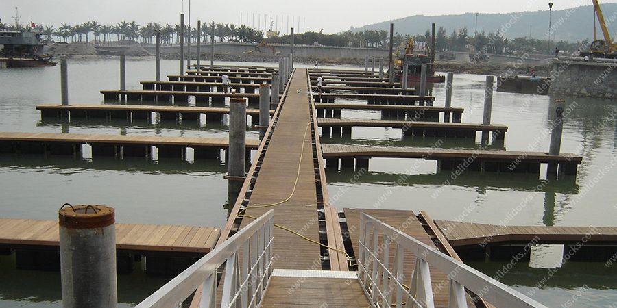
The choice between fixed pile-supported structures and floating systems dictates foundation design, utility integration, and maintenance protocols. Each configuration has distinct engineering requirements.
Fixed structures rely on driven piles—steel pipe, precast concrete, or timber—transmitting loads to competent bearing strata. Design considerations include:
Lateral load resistance: Batter piles (raked at 15-20 degrees) provide resistance to berthing forces and wind loads, particularly critical in exposed locations
Scour protection: Riprap or articulated concrete blocks installed around pile groups prevent loss of soil support from propeller wash and wave action
Seismic design: In high-seismic zones, piles must accommodate ground motion through ductile detailing, often utilizing steel pipe piles with concrete infill
Floating structures accommodate water level fluctuations up to 10 feet or more, making them mandatory for tidal zones and reservoirs with significant drawdown. Engineering considerations include:
Pontoon design: Rotational-molded polyethylene for light-duty applications; reinforced concrete or welded aluminum for commercial-grade facilities
Pile guidance systems: Galvanized steel frames with low-friction polyethylene bushings that allow vertical travel while restraining lateral movement
Anchorage: Deadman anchors, helical piles, or spud poles sized to resist wind loads per ASCE 7-16 standards
Hybrid systems are increasingly specified for large facilities, combining a fixed marginal wharf for utilities and vehicle access with floating outer basins for vessel berthing. This approach minimizes environmental footprint while maximizing operational flexibility.
Modern waterfront construction extends beyond structural elements to encompass sophisticated utility networks. The integration of electrical, water, and data systems requires coordination with structural components to ensure long-term reliability.
All electrical installations must conform to NFPA 70 (National Electrical Code) Article 555 for marine facilities. Critical requirements include:
Ground-fault protection on all feeders supplying dock power (30 mA trip threshold)
Corrosion-resistant enclosures rated for wet locations (Type 4X)
Separately derived systems for shore power with isolation transformers to eliminate galvanic stray currents
Potable water distribution requires backflow prevention at each service connection to prevent contamination of municipal supplies. For fire protection, NFPA 303 mandates hydrant spacing based on facility layout, typically not exceeding 300 feet between hydrants. Systems must accommodate freeze protection in cold climates through heat trace cables or automatic drain-down valves.
Conduit systems for fiber optic and coaxial cable should be installed during initial construction rather than retrofitted. Specifications typically include:
Schedule 80 PVC conduit with sweeping bends to accommodate fiber bend radius requirements
Pull boxes at 200-foot intervals for future cable installation
Separate pathways for power and data to prevent electromagnetic interference
Projects that incorporate these utilities during the initial decks and docks construction phase avoid the 40-60% cost premium associated with retrofitting completed structures.
Waterfront infrastructure faces distinct operational challenges that demand proactive engineering responses rather than reactive maintenance approaches.
Galvanic corrosion occurs when dissimilar metals are electrically connected in an electrolyte (saltwater). Prevention strategies include:
Dielectric isolation fittings between steel piles and aluminum deck framing
Sacrificial anode systems (zinc or aluminum) calculated to provide 20-year protection intervals
Coating systems with documented adhesion in immersion service (AWWA C210 for steel)
Vessel-generated waves erode shorelines and undermine structural foundations. Engineered countermeasures include:
Floating breakwaters with reinforced concrete or steel hulls, positioned to create quiet water zones
Reef blocks or geotextile bags placed at scour-critical locations
Vegetated riprap slopes that provide habitat value while stabilizing shorelines
ADA Title III requires accessible routes to all public waterfront facilities. In tidal applications, this necessitates:
Floating gangways with self-adjusting hinges that maintain maximum 1:12 slope at all tide levels
Landing platforms sized for wheelchair turning radius (60-inch minimum)
Surface materials with slip-resistant properties meeting ASTM F1679 standards
Firms specializing in decks and docks construction incorporate these solutions during design, recognizing that field modifications after construction rarely achieve the same level of integration.

Regulatory approval represents one of the most significant risks in waterfront construction timelines. Successful projects anticipate agency requirements and incorporate compliance measures into the construction methodology.
In the United States, Section 404 permits from the Army Corps of Engineers govern dredge and fill activities. State-level coastal zone management programs impose additional conditions. Typical permit requirements include:
Biological assessments documenting impacts to protected species (sea turtles, manatees, salmonids)
Turbidity monitoring during in-water work, with thresholds typically set at 50 NTU above background levels
Seasonal work windows that avoid critical spawning or nesting periods
Low-impact construction techniques reduce permitting complexity and community opposition:
Bubble curtains or cofferdams for pile driving noise attenuation
Silt curtains with weighted skirts to contain suspended sediment
Helical pile installation that generates no spoils or vibration compared to driven piles
Institutional investors and marina owners increasingly evaluate waterfront infrastructure through total cost of ownership (TCO) models. A comprehensive TCO analysis reveals that initial capital expenditure represents a fraction of 50-year costs.
Timber: Annual inspections, recoating every 2-3 years, structural repairs every 10-15 years
Aluminum: Biennial inspections, coating touch-ups every 5-7 years in saltwater
Concrete: Quinquennial inspections, major repairs every 30-40 years if properly specified
Facilities constructed to current codes (ASCE 7-16 wind loads, NFPA 303 fire protection) often qualify for reduced property insurance premiums. Documentation of material certifications and inspection protocols supports underwriting evaluations.
Collaborating with experienced engineers and contractors—such as those affiliated with DeFever—ensures that lifecycle considerations are embedded in the design phase rather than addressed through costly retrofits.
Successful waterfront infrastructure requires integration of material science, structural engineering, utility planning, and regulatory compliance. Owners and developers who prioritize engineered solutions over generic construction practices achieve assets that withstand environmental forces, meet accessibility standards, and deliver predictable lifecycle costs. Engaging with specialists who understand the technical demands of decks and docks construction ensures that the final facility serves as a durable, income-producing asset rather than a recurring maintenance obligation.
A1: The primary determinant is water level fluctuation. Fixed docks are suitable when water level variation is less than 3 feet annually (typical of reservoirs with controlled releases or inland lakes). Floating docks are required when tidal ranges exceed 3 feet or when reservoirs experience significant drawdown. Secondary considerations include soil conditions (floating systems reduce pile requirements) and vessel types (floating docks provide consistent freeboard for boarding regardless of water level).
A2: Request material certifications and third-party test reports. For concrete, demand documentation of mix design, compressive strength tests (ASTM C39), and rapid chloride permeability results (ASTM C1202). For steel components, verify coating specifications against manufacturer data sheets and request mill certificates confirming alloy composition. For timber, require treatment certification from the American Wood Protection Association. Contractors who cannot provide these documents typically lack quality control protocols.
A3: The three most common failure mechanisms are: (1) galvanic corrosion at dissimilar metal connections—prevented by dielectric isolation and sacrificial anodes; (2) fastener failure from inadequate material selection—prevented by specifying Type 316 stainless for all submerged fasteners; (3) pile settlement from scour—prevented by geotechnical investigation and installation of scour protection during construction. These failures typically become apparent 5-10 years post-construction and require costly remediation.
A4: For projects requiring federal permits (Army Corps of Engineers Section 404 or Section 10), permitting typically requires 8-14 months, often exceeding construction duration. State and local permits may add additional 3-6 months. Project schedules should allocate 50% of total timeline to pre-construction permitting activities. Early consultation with regulatory agencies and engaging environmental consultants during design significantly reduces permitting delays.
A5: Professional firms should provide: (1) a minimum one-year workmanship warranty covering installation defects; (2) manufacturer warranties for major components (floating pontoons typically carry 10-20 years, aluminum framing 10 years); (3) as-built drawings showing pile locations, conduit routing, and utility connections; (4) operation and maintenance manuals with inspection intervals and replacement part specifications; (5) warranty registration documentation for transfer to future property owners. Absence of these documents indicates limited quality assurance processes.
