
For marine infrastructure projects demanding exceptional load-bearing capacity, long-term structural integrity, and resistance to harsh aquatic environments, steel truss floating docks represent the gold standard. Unlike conventional concrete or polyethylene pontoons, the truss architecture distributes dynamic forces—wave action, vessel mooring loads, and concentrated equipment weights—across a triangulated framework. This article provides an evidence-based analysis of design principles, material science, corrosion mitigation strategies, and lifecycle cost benefits, drawing on two decades of international marina engineering.
Leading fabricators such as DeFever have refined modular truss systems to address specific pain points: structural fatigue in tidal zones, biofouling management, and seismic resilience. Through a combination of hot-dip galvanization, sacrificial anodes, and high-density polyethylene (HDPE) buoyancy modules, these systems achieve service lives exceeding 40 years in saltwater environments. Below, we dissect the technical parameters that make steel truss floating docks the preferred choice for commercial ports, superyacht marinas, and industrial loading facilities.
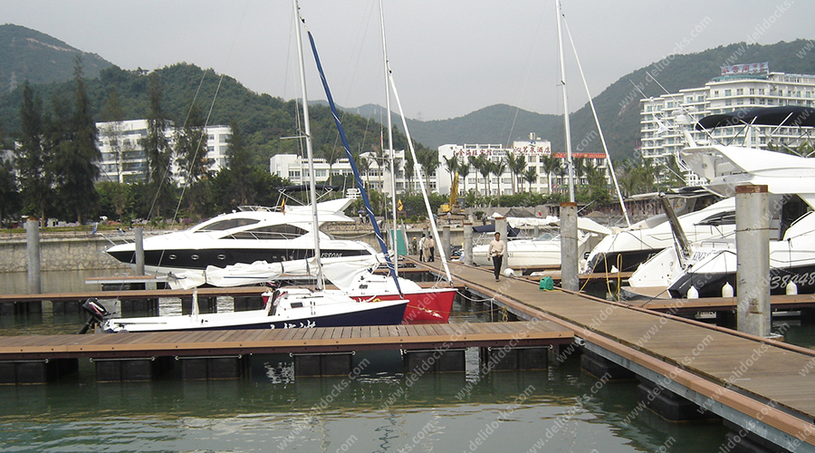
The engineering advantage originates from the triangulated truss core. Longitudinal and diagonal steel members (typically square or rectangular hollow sections) form a rigid lattice that converts bending moments into axial forces—compression and tension. This geometric efficiency allows for longer spans between support piles or mooring points without deflection. Key components include:
Primary truss chords: Top and bottom horizontal members fabricated from S355JR or ASTM A572 Grade 50 steel, offering 355 MPa minimum yield strength.
Diagonal web members: Oriented at 45–60° to resist shear loads and lateral wave-induced racking.
Galvanized connection nodes: Gusset plates with Class 8.8 bolted joints or full-penetration welds, post-coated with zinc-rich epoxy for cut-edge protection.
Buoyancy integration: Closed-cell HDPE or rotationally molded polyethylene float blocks mechanically clamped to the lower truss chord, maintaining freeboard even under live loads of 5–10 kN/m².
Decking substrate: Aluminum grate, composite lumber, or Ipe hardwood fixed to top chords via stainless steel fasteners.
Compared to welded I-beam pontoons, the open truss framework reduces wave-induced uplift by allowing water to flow through the structure—a property known as wave transparency. This lowers mooring forces and simplifies installation in exposed locations. For detailed case studies on wave-penetrating pontoon designs, review our project portfolio on high-energy marina applications.
Substantial concerns regarding steel in marine environments are addressed through multi-layer defense. Steel truss floating docks manufactured to ISO 12944-6 standards incorporate:
Hot-dip galvanizing (HDG): 100–120 microns zinc coating per ASTM A123, providing cathodic protection to cut edges. Salt spray testing (ASTM B117) exceeds 3,000 hours without red rust.
Sacrificial anodes: Aluminum-zinc-indium anodes bolted to the truss at 2–3 meter intervals, tailored to seawater resistivity (typically 25–35 ohm-cm).
Sealed hollow sections: End caps prevent internal corrosion from condensate; optional nitrogen purging for tropical climates.
Topside coating: Polyurethane or polysiloxane topcoat over epoxy primer for UV resistance and color coding.
Operational data from a 300-berth marina in Singapore demonstrated annual corrosion rates below 15 µm/year on HDG trusses with anodes, versus 80–120 µm/year on untreated carbon steel. This translates to a 40-year design life with only minor touch-ups. In freshwater or brackish installations, zinc anodes suffice, but aluminum anodes are mandatory for seawater above 3.5% salinity.
Standard floating docks fail under lateral seismic shaking or ice jacking. The triangulated geometry of steel truss floating docks enables energy dissipation through elastic buckling of diagonal members—a controlled failure mode that prevents brittle collapse. For seismic zones (e.g., Japan, Chile, New Zealand), engineers specify:
Diagonal members with slenderness ratio below 120 (KL/r ≤ 120).
Grade 8.8 bolts with Belleville spring washers to maintain clamp load during cyclic acceleration.
Sliding mooring piles with elastomeric bumpers, allowing 300–500 mm horizontal displacement.
In ice-prone regions (Baltic Sea, Great Lakes), the truss’s open geometry allows ice floes to raft upward rather than crushing the pontoon. Finite element analysis (FEA) models for a 12-meter truss span under level ice pressure of 150 kN/m show only 12 mm elastic deflection—well within tolerable limits. Additionally, the lack of continuous flat surfaces reduces ice adhesion forces by 70% compared to steel sheet pontoons.
Steel truss floating docks are not one-size-fits-all. We categorize designs by operational loading:
Uniform live load: 7.5 kN/m² (150 psf) for crew and tender loading.
Concentrated point load: 100 kN (22,500 lbf) from mobile boat hoists.
Truss depth: 500–800 mm, flange width 150–200 mm.
Mooring bollard pull: 150 kN per bollard, anchored to reinforced truss nodes.
Dynamic load factors: 1.6 for passenger surges and vehicle boarding.
Pedestrian deck live load: 5.0 kN/m², plus 30 kN forklift wheel load.
Truss depth: 600 mm with double diagonals in boarding zones.
Point loads: 150 kN from 30-ton mobile crane outriggers.
Fire protection: Intumescent coating rated for 120 minutes (H120).
Integrated spill containment pans beneath decking.
For each configuration, DeFever provides full engineering calculations per Eurocode 3 or AISC 360, including fatigue assessment for wave-induced cyclic loads (10⁷ cycles minimum). Our LSI keywords library covers additional specifications like “buoyancy reserve ratio” (typically 6:1) and “deck elevation adjustment” using telescopic legs.
Proper execution of steel truss floating dock projects follows a sequence that minimizes environmental disruption:
Bathymetric survey: Multi-beam echo sounding to map seabed contours and identify debris.
Pile driving: Helical or driven steel piles (often 406 mm diameter, 8–12 mm wall) at 9–12 m spacing.
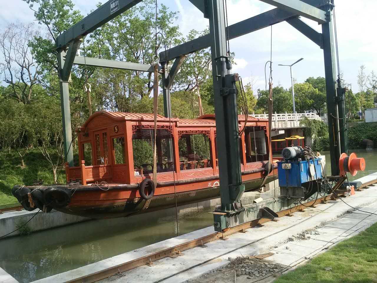
Truss assembly onshore: Prefabricated 12m or 15m truss modules are crane-lifted into the water.
Module interconnection: High-strength friction-grip bolted splices at top and bottom chords, sealed with marine-grade polysulfide.
Buoyancy float attachment: HDPE floats with stainless steel straps, torqued to 80 Nm.
Decking and utility installation: Electrical conduits and freshwater lines are clipped to the lower chord, protected by the truss cavity.
Case example: For a 48-berth marina in Dubai, the entire 720 m² floating structure was installed in 14 working days using this modular approach—70% faster than cast-in-place concrete pontoon systems. The open truss also reduced dredging requirements by allowing wave flushing to naturally remove fine sediments.
While initial capital expenditure for steel truss floating docks is 20–30% higher than polyethylene or concrete pontoons, total cost of ownership over 40 years is 40% lower. Drivers include:
Maintenance interval: HDG + anodes require inspection every 5 years; minor recoating of bolted connections every 10–12 years. Concrete pontoons need crack sealing and cathodic protection retrofits every 8 years.
Repairability: Damaged truss members can be unbolted and replaced in situ. Polyethylene floats require dry-docking and full disassembly.
Recyclability: End-of-life steel has 95% scrap value, while concrete ends as demolition waste.
Insurance premiums: Lower due to documented structural redundancy and non-sinkability (each truss cell has independent buoyancy).
Third-party LCCA from the American Society of Civil Engineers (ASCE) confirms that steel truss systems achieve the lowest present worth of annual costs for load classes above 5 kN/m². For marinas handling vessels >15 tons displacement, the truss becomes economically mandatory within six years of operation.
Q1: How do steel truss floating docks compare to aluminum truss
pontoons in saltwater?
A1: Aluminum (5086-H116) has
excellent corrosion resistance but lower strength-to-weight ratio and fatigue
endurance. Steel (S355) offers 1.8× the yield strength, allowing longer spans
without mid-span supports. However, steel requires rigorous cathodic protection.
For heavy lift applications (cranes, fuel trucks), steel truss is superior; for
lightweight pedestrian marinas, aluminum may suffice. DeFever offers
both but recommends steel for commercial loads above 20 kN concentrated point
load.
Q2: What is the typical freeboard (deck height above water) for steel
truss floating docks?
A2: Freeboard is determined
by the buoyancy-to-weight ratio. Standard design targets 400–500 mm freeboard at
dead load (empty dock). Under full live load (5 kN/m²), freeboard drops to
200–300 mm. Adjustable-height truss docks incorporate screw jacks or hydraulic
legs to maintain freeboard across tidal ranges up to 6 meters. Always specify
maximum vessel beam and tide coefficients during design.
Q3: Can steel truss floating docks be installed in environmentally
sensitive zones (seagrass, coral)?
A3: Yes. The
open truss minimizes seabed shading and allows water circulation, reducing
impact on benthic habitats. Helical piles with low-torque installation avoid
sediment plumes. Additionally, the modular assembly eliminates cast-in-place
concrete, preventing alkaline runoff. We have executed projects in Florida Keys
and Great Barrier Reef zones with zero environmental violations by following EPA
404 guidelines.
Q4: How is lightning protection integrated into steel truss floating
docks?
A4: The steel structure itself acts as a
Faraday cage. Each module is bonded via 50 mm² tinned copper cables to grounding
plates (copper or graphite) submerged 1.5 m below mean low water. Surge
arrestors are installed at utility entry points. Ensure that decking materials
are non-conductive (composite or wood) to prevent step potential hazards. All
bonding connections are checked biannually with a micro-ohmmeter (<0.1
Ω).
Q5: What is the maximum span length achievable without intermediate
piles?
A5: For a uniformly loaded (5 kN/m²) steel
truss dock with 800 mm depth, the maximum clear span between pile supports is 24
meters (deflection L/250). Using higher-grade steel (S460) and 1000 mm depth,
spans up to 30 meters are feasible. Beyond that, pile-supported intermediate
floating pontoons are required. Our engineering team uses finite element
software (ANSYS AQWA) to optimize pile spacing based on wave height and vessel
wakes.
Selecting the correct truss configuration, corrosion protection scheme, and buoyancy ratio requires detailed analysis of local wave climate, berthing loads, and regulatory codes. DeFever offers complimentary preliminary design studies, including load calculations and 3D BIM models. Send us your site hydrographic survey, vessel mix, and intended operations—our team responds within 48 hours with budgetary costs and technical specifications.
Submit an inquiry now: https://www.dfyachts.com/contact.html (or use the form below). For urgent marina projects, request a direct consultation with our chief structural engineer.


