
For marina operators, civil marine contractors, and waterfront developers, the shift from fixed concrete structures to engineered portable floating dock systems represents a fundamental change in asset management. These modular platforms eliminate costly dredging, adapt to seasonal water fluctuations, and permit rapid reconfiguration. This article examines technical specifications, connection mechanics, material science, and real-world deployment scenarios—providing a reference for procurement and engineering teams.
Designing a resilient floating dock requires balancing buoyancy, stiffness, and environmental loads. Unlike permanent piers, portable floating dock systems rely on distributed flotation and interlocking connections. Below are the critical parameters engineers evaluate during site assessment.
Each floating module must support dead load (self-weight) plus live load (pedestrian, forklift, or small crane). Industry practice for commercial marinas specifies a minimum freeboard of 300–450 mm under maximum load. Buoyancy units—typically rotationally molded polyethylene (PE) or closed-cell EPS foam encased in concrete—are specified by volume displacement. For a 6m x 3m dock section, target a buoyancy reserve exceeding 150% of anticipated maximum load to account for wave action and asymmetric loading.
Three connection types dominate professional applications:
Steel hinge connectors: Allow angular movement up to ±15° for wave compliance, suitable for exposed basins.
Elastomeric torsion couplings: Provide damping against repeated impact loads (mooring vessels).
Interlocking extruded aluminum rails: Rigid lateral alignment, used for high-precision equipment launches.
Selection depends on significant wave height (Hs) and berthing energy. For sheltered inland marinas (Hs<0.3m), polyethylene pin connectors offer adequate performance at lower mass.
Traditional pile-supported docks present recurring operational issues. Engineered floating alternatives solve these through modularity and low draft requirements.
Fixed docks require periodic dredging to maintain navigable depths—an expense frequently exceeding $200,000 per hectare. Portable floating dock systems draw as little as 0.4m, allowing operation in silting basins. Draft adjustment is achieved by adding/subtracting buoyancy modules or altering ballast.
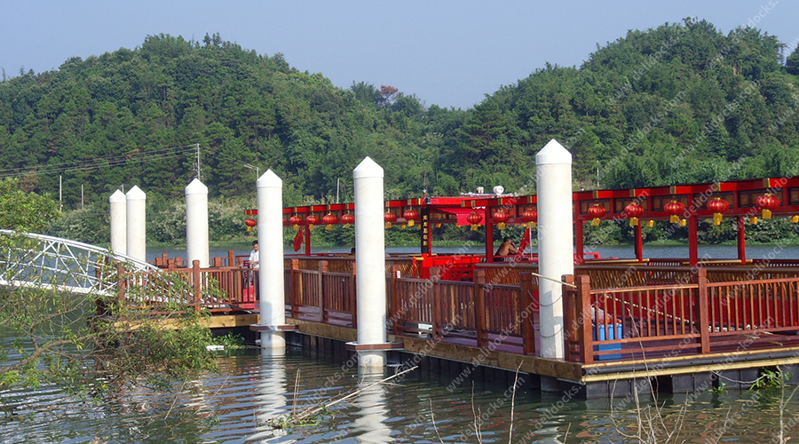
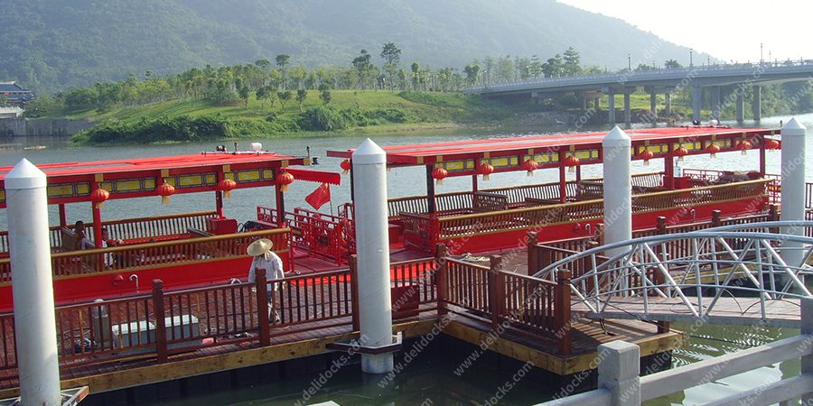
Reservoirs and tidal zones see vertical changes of 2–8m annually. Floating docks follow water surface automatically without mechanical lift systems. Case example: a hydropower reservoir with 6m drawdown range—floating gangways with articulating hinges maintained continuous access, whereas fixed ramps required seasonal reconstruction.
In many jurisdictions, floating structures are classified as “temporary works” if no piling or seabed alteration occurs. This reduces approval timelines from 18 months to 8 weeks. Moreover, the absence of submerged concrete avoids benthic habitat destruction.
Following storm damage or for seasonal events (boat shows, fishing tournaments), contractors need 48-hour installation. Pre-assembled floating dock sections—sized for flatbed trucks—are craned into place and connected via drop-in pins. Reverse logistics for removal are identical.
Corrosion, UV degradation, and impact resistance determine lifecycle costs. For commercial marinas (design life >20 years), material combinations require careful specification.
Superstructure options:
Marine-grade aluminum (6061-T6 or 5083-H116): Best weight-to-strength ratio, naturally resistant to saltwater corrosion. Welded or bolted frames for crane running beams.
Galvanized steel: Higher stiffness for heavy vehicle access (forklifts up to 8t), but requires annual coating inspection. Not recommended for tropical saltwater.
Recycled plastic composites: No corrosion, low maintenance, but limited flexural modulus—suitable for pedestrian pontoons only.
Flotation core comparison:
Rotomolded PE tanks (filled with EPS): Impact-resistant, repairable in situ. Check for UV-stabilized grade (≥ 2% carbon black).
Uniblock EPS (17–24 kg/m³ density): Lightweight, but requires protective skin to avoid boat propeller damage.
Concrete pontoons with foam core: Very high inertial mass—reduce wave-induced motion but require heavy equipment for repositioning.
For high-traffic yacht marinas, DeFever specifies aluminum superstructures with PE float tanks, achieving both corrosion resistance and buoyancy redundancy. Each module is pressure-tested to 1.5x working load before dispatch.
Beyond conventional marinas, engineering teams apply portable floating dock systems in several specialized environments.
For bridge or waterfront building projects, floating docks serve as equipment platforms for piling rigs, concrete pumps, and temporary crew quarters. System requirements differ: deck load ratings must exceed 25 kN/m², and mooring systems need hold-off forces against tug wakes. Modular steel deck sections with integrated crane pads are available.
Water quality sensors, flow meters, and sediment samplers benefit from stable, non-permanent platforms. Floating docks allow relocation as monitoring priorities shift. Electrical conduits within the dock frame keep cables dry and protected from ice damage.
Following flood damage to fixed infrastructure, floating docks provide immediate passenger access. A 30-meter floating pier can be deployed within 12 hours from containerized storage. Anchor systems use helical screw piles or deadweight concrete blocks, avoiding disturbance to buried utilities.
Professional floating berths need water, power, data, and sewage pump-out. Designers incorporate articulated utility bridges that follow dock movement. Key components:
Hinged gangways with integrated cable trays: Allow pitch and roll while protecting hoses.
Quick-disconnect water/power pedestals: Mounted on the floating deck with flexible jumper lines to shore.
Slip rings or catenary cables: For large tidal ranges, catenary loops of power/data lines prevent tension damage.
These features transform simple floating docks into fully functional marina fingers.
To achieve 30-year service life, operators follow interval-based inspection:
Quarterly: Check connection bolts for torque loss. Inspect polyethylene floats for abrasion or puncture.
Annually: Ultrasonic thickness measurement on aluminum welds (critical for high-load zones). Replace sacrificial anodes.
Every 5 years: Pressure test buoyancy tanks to detect micro-leaks. Re-coat galvanized components if needed.
Most repairs can be performed with the dock afloat—defective flotation modules are swapped using a lifting bag or service crane.
When a project demands high-departure from standard catalog products—such as reinforced deck areas for mobile cranes, curved sections for wave attenuation, or negative freeboard for vessel maintenance—DeFever provides custom engineering. Their design workflow includes finite element analysis for load cases, 3D hydrology simulations, and modular production that ships to remote sites. Over 14 years, their delivered portable floating dock systems have operated in tidal ranges from 0.5m to 9m, with ice thickness up to 0.6m using bubbler systems.
Q1: What are the maximum wave heights that portable floating dock
systems can accommodate without structural
fatigue?
A1: For standard modular systems (PE
floats + aluminum frame), sustained significant wave height Hs = 0.6m is safe
for normal operations. With reinforced cross-bracing and deep-V hull profiles,
some designs tolerate Hs up to 1.2m, but moored vessels will experience motion.
Above 1.5m, berthing is not recommended. Always check the manufacturer’s design
wave criteria.
Q2: Can these floating docks be anchored in soft mud or silty
lakebeds without traditional piles?
A2: Yes. Two
methods are common: (1) helical screw anchors with 2-3m embedment into cohesive
soils, using flexible chains to the dock; (2) concrete deadweight anchors
(500-1500 kg each) placed on the bed, installed by divers or hydraulic arms. Mud
penetration is limited, but lateral drift requires calculating holding capacity
per anchor.
Q3: How are portable floating dock systems modified for heavy
forklifts (up to 6 tons) used in boatyard
operations?
A3: The deck must be designed with
concentrated load patches. Use aluminum I-beam stringers at 300 mm centers and
double-thick (12mm) aluminum deck plates. Additionally, provide longitudinal
stiffening beams under forklift travel paths. Flotation is increased by 40%
compared to standard docks, often using dual-layer PE floats.
Q4: Are there fire safety requirements for floating marinas using
modular plastic floats?
A4: Yes, NFPA 303 and local
codes apply. Polyethylene floats are combustible but can be protected by (a)
maintaining 2m separation between dock sections to create fire breaks, (b) using
water mist systems from marina hydrants, or (c) applying intumescent coatings on
exposed float surfaces. For high-risk refueling docks, specify concrete
floatation.
Q5: What electrical grounding strategy is used for floating docks
with shore power pedestals?
A5: Floating structures
are electrically isolated from shore ground (earth). A dedicated copper
grounding ring is embedded in the dock structure, connected to shore ground via
a flexible tinned-copper strap that spans the gangway. Each power pedestal has
its own ground fault protection (30mA trip). Potential equalization bonding
between all metal components prevents stray current corrosion.
For site-specific engineering analysis—including load calculations, anchoring system selection, and custom deck layouts—contact the marine infrastructure team at DeFever. Provide water depth variation, predominant vessel types, and soil investigation reports (if available). A preliminary structural design and installation sequence will be returned within 10 working days.
Send inquiries to: https://www.dfyachts.com/contact.html | Quote reference “modular dock spec” for priority handling.

